
LLMs and Agents
An in-depth research report entitled Investigation_into_Large_Language_Models, Their_Interfaces,_and_use_as_Agents was authored by The Engineer to report his study of Large Language Models (LLMs) and their application as autonomous agents. His research initially explored OpenAI's LLMs, which led to the discovery of smaller, locally-hosted LLMs and their supporting interfaces. The investigation was then expanded to evaluate the performance of these local models using various compatible frameworks, ultimately demonstrating their capability to function as higher-level autonomous agents.Two Cooperative AI Agents
Two AI agents working together to conduct scientific research, then writing their findings in a blog format have been programmed and demonstrated by The Engineer. These agents, at the time of operation, were both based on a Large Language Model (LLM) named OpenHermes. That model was fine-tuned on a Mistral model, then quantized to 7B size, yet has been shown to perform like a 70B model on benchmarks. The two agents were assigned roles of 'Senior Research Analyst' and 'Tech Content Strategist' with qualifying backstory credentials. Their tasks were to conduct online research on the latest life-extension technologies, and to analyze and provide a blog narrative outlining their findings.Key aspects included:
Wireless Power Transfer System
A Wireless Power Transfer System providing electrical energy transmission using a transmitter and separated receiving circuit has recently been completed by The Engineer. Starting with basic generally expected specifications for such a system, it was designed in two phases: 1. Initial transmitter and receiver breadboards were built for researching technical issues. 2. Refined transmitter and receiver PCBs were laid out using reference designs, researched solutions, and industry standard practices, then built and tested in version subphases.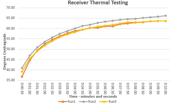 Development of the receiver was started with an open reference circuit provided by Analog Devices, then modified for
the applicaton. The PCB layout was then done by The Engineer using KiCad tools. The layout was subsequently fabbed, built, tested and verified
against generally expected specifications for this advanced Synchronous Regulator design.
Thermal testing at full power (see graphic example) was undertaken to verify a wide range of performance conditions
under load.
A
small millimeter-sized prototype reciever was then built for further integration and testing by the client company.
Development of the receiver was started with an open reference circuit provided by Analog Devices, then modified for
the applicaton. The PCB layout was then done by The Engineer using KiCad tools. The layout was subsequently fabbed, built, tested and verified
against generally expected specifications for this advanced Synchronous Regulator design.
Thermal testing at full power (see graphic example) was undertaken to verify a wide range of performance conditions
under load.
A
small millimeter-sized prototype reciever was then built for further integration and testing by the client company.
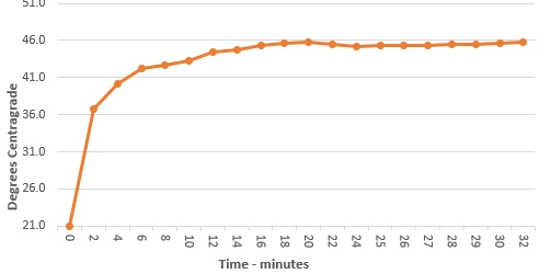 Meanwhile a third revision transmitter had been completed by The Engineer to meet improved physical and operational
performance requirements. The transmitter development had been undertaken using a well known H-Bridge design and followed the same multi-stage process as the receiver,
including full power thermal testing
(see graphic example).
Transmitter drive frequency requirements needed to be
carefully chosen, as specified in reference
documentation provided by Wurth Elektronic "Trilogy"[1].
Adhering to this standard allowed a wide dynamic range
for power transfer, as well as allowing it to stay within component-based
upper and lower limits of the system design. Also based upon
the reference recommendations, a tunable digital
oscillator was integrated into the transmitter allowing adjustment for testing, and to later fix the output drive frequency at an ideal point to satisfy any generally expected manufacturing
and calibration requirements.
Magnetic shielding was also provided to protect the transmitter PCB from stray field eddy currents.
Meanwhile a third revision transmitter had been completed by The Engineer to meet improved physical and operational
performance requirements. The transmitter development had been undertaken using a well known H-Bridge design and followed the same multi-stage process as the receiver,
including full power thermal testing
(see graphic example).
Transmitter drive frequency requirements needed to be
carefully chosen, as specified in reference
documentation provided by Wurth Elektronic "Trilogy"[1].
Adhering to this standard allowed a wide dynamic range
for power transfer, as well as allowing it to stay within component-based
upper and lower limits of the system design. Also based upon
the reference recommendations, a tunable digital
oscillator was integrated into the transmitter allowing adjustment for testing, and to later fix the output drive frequency at an ideal point to satisfy any generally expected manufacturing
and calibration requirements.
Magnetic shielding was also provided to protect the transmitter PCB from stray field eddy currents.
 A prototype transmit-receive demo
system was also provided to the client for continued testing and further integration as desired to meet company objectives.
Additionally, a comprehensive Wireless Charging Demo System Calibration test procedure document was written for use in verification of a new “unit under test” to insure the critical operational voltage parameters on that unit.
A prototype transmit-receive demo
system was also provided to the client for continued testing and further integration as desired to meet company objectives.
Additionally, a comprehensive Wireless Charging Demo System Calibration test procedure document was written for use in verification of a new “unit under test” to insure the critical operational voltage parameters on that unit.
Medical Device MICS Starter System and Software
 A bare-bones medical implant
starter platform is being created by The Engineer to
provide the basic framework necessary to begin
development of a GUI, Base Station, and Implant medical
device. The Host GUI is coded in C# and represents a
simple interface with basic features providing CRC
protected command packets. The Base Station uses a
state-driven synchronous operating system and relies
upon a general command and response regimen (one command
– response pair at a time), with RF protocol handled by
a ZL70123 module. The Implant uses a FreeRTOS operating
system for receiving over-the-air commands, processing
them for intended therapy and data collection, and
response generation for transmission back via Base
Station to the Host GUI, with all RF protocol handled by a ZL70321 (or
available miniature ZL70323) module.
A bare-bones medical implant
starter platform is being created by The Engineer to
provide the basic framework necessary to begin
development of a GUI, Base Station, and Implant medical
device. The Host GUI is coded in C# and represents a
simple interface with basic features providing CRC
protected command packets. The Base Station uses a
state-driven synchronous operating system and relies
upon a general command and response regimen (one command
– response pair at a time), with RF protocol handled by
a ZL70123 module. The Implant uses a FreeRTOS operating
system for receiving over-the-air commands, processing
them for intended therapy and data collection, and
response generation for transmission back via Base
Station to the Host GUI, with all RF protocol handled by a ZL70321 (or
available miniature ZL70323) module.
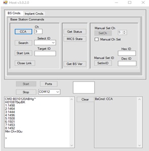
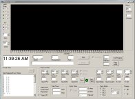
The Host system GUI (running on a PC) allows sending
commands to the Base Station or Implant following its RF
link establishment. An example Clear Channel Assessment
(CCA) requested by the Host is shown in figure to left, with
response measurement of channel noise in the MICS band
choosing channel 3. Search,
Authentication, and link connection are all undertaken
at user request, after which commands may be sent
over-the-air to the Implanted device. Basic Implant
commands are implemented to demonstrate the methods
used for over-the-air command processing and response back to the
connected host for further processing as desired.
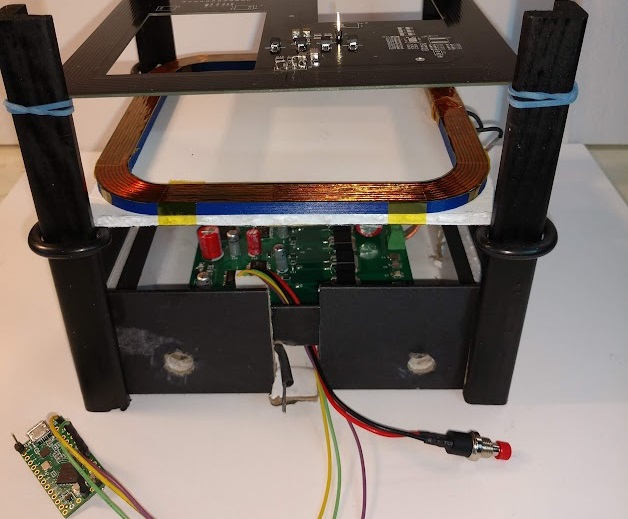
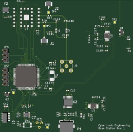 System hardware consists of the Base Station printed
circuit layout, shown in figure at left, using a Texas
Instruments MSP430F2618 Microcontroller working with the
Microsemi ZL70123 Base Station module under firmware
control.
System hardware consists of the Base Station printed
circuit layout, shown in figure at left, using a Texas
Instruments MSP430F2618 Microcontroller working with the
Microsemi ZL70123 Base Station module under firmware
control.
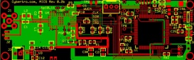 The Implant demonstration module printed circuit layout, shown in figure at right, uses the Texas
Instruments MSP430F5359 Microcontroller and ZL70321 (or could use a micro sized ZL70323),
capable of very low power
operation during the overall idle and communication cycle.
The demo Implant board circuit can be significantly reduced
in size (for in vivo testing) using flex circuitry and the ZL70323
.
The Implant demonstration module printed circuit layout, shown in figure at right, uses the Texas
Instruments MSP430F5359 Microcontroller and ZL70321 (or could use a micro sized ZL70323),
capable of very low power
operation during the overall idle and communication cycle.
The demo Implant board circuit can be significantly reduced
in size (for in vivo testing) using flex circuitry and the ZL70323
.
The Engineer, J. Brennan, at
Cybertronic Engineering (Cybertro.com) has been
designated as an “Authorized Subcontractor” by Microsemi
Semiconductor (U.S.) Inc., to work on and integrate its
software into licensee products. The Foregoing described
software was developed as a MICS demonstration system under
this authorization for purposes of integration into
products being developed by a Licensee company.
Medical Device Radiocommunications Service
Starter System.html
Prototype Implant and Base Station Controller
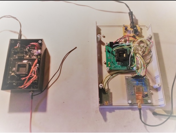 The Engineer helped design sections of a prototype laser
therapy device, intended for eventual implantation in
the human body, as well as designing a matching wireless
Base Station controller. This system was initially
intended to conduct bench experiments,
circuit debugging, and embedded software control for
further development of the implant and its radio link. The implantable device was based upon a Texas
Instruments MSP430 processor controlling a Microsemi
ZL70321 MICS-Band RF Implant Module. The Base
Station was designed using a similar Texas Instruments MSP430 processor
controlling a Microsemi ZL70120 MICS-Band RF Telemetry Radio module.
The Engineer helped design sections of a prototype laser
therapy device, intended for eventual implantation in
the human body, as well as designing a matching wireless
Base Station controller. This system was initially
intended to conduct bench experiments,
circuit debugging, and embedded software control for
further development of the implant and its radio link. The implantable device was based upon a Texas
Instruments MSP430 processor controlling a Microsemi
ZL70321 MICS-Band RF Implant Module. The Base
Station was designed using a similar Texas Instruments MSP430 processor
controlling a Microsemi ZL70120 MICS-Band RF Telemetry Radio module.
 The Engineer developed all of the
initial C language prototype test and debug firmware for both implant and Base Station to provide
a whole system communication link for over-the-air testing on a multitude of implant peripherals.
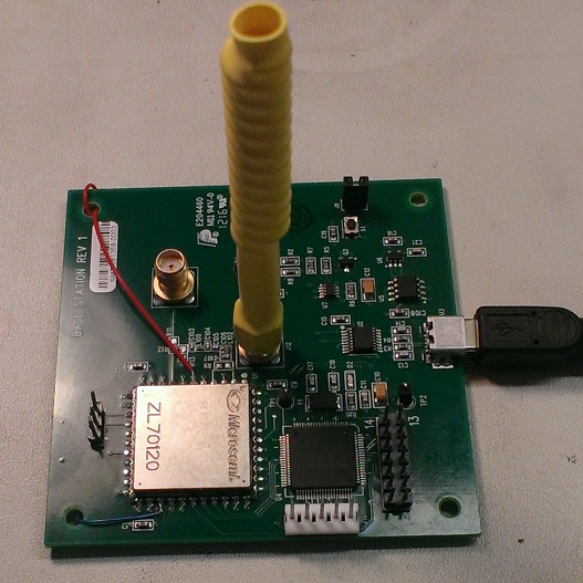
The Engineer also designed the control sections of a
second prototype revision Base Station to use a
Microsemi ZL70123, as well as sections of the
second revison iC-NZP based laser control circuitry for
the implant. An extensive software architecture redesign
was then specified by company engineering, and
subsequently implemented in the Base Station firmware by
The Engineer using a "Pycca" framework to provide it with a full featured
state driven operating system. Additional Host PC based prototype software, written in C#, was also developed by The Engineer
to facilitate a test GUI for the newly implemented Base
Station-to-Implant communications system. The Engineer
subsequently provided some design input to, and full firmware implementation
of, a third generation miniturized Base Station
using the Microsemi ZL70123 for advanced stages of radio communications testing.
The Engineer developed all of the
initial C language prototype test and debug firmware for both implant and Base Station to provide
a whole system communication link for over-the-air testing on a multitude of implant peripherals.
The Engineer also designed the control sections of a
second prototype revision Base Station to use a
Microsemi ZL70123, as well as sections of the
second revison iC-NZP based laser control circuitry for
the implant. An extensive software architecture redesign
was then specified by company engineering, and
subsequently implemented in the Base Station firmware by
The Engineer using a "Pycca" framework to provide it with a full featured
state driven operating system. Additional Host PC based prototype software, written in C#, was also developed by The Engineer
to facilitate a test GUI for the newly implemented Base
Station-to-Implant communications system. The Engineer
subsequently provided some design input to, and full firmware implementation
of, a third generation miniturized Base Station
using the Microsemi ZL70123 for advanced stages of radio communications testing.
Wireless Cardiac Pacemaker
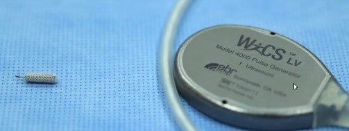 Full-Time systems/software engineer at EBR Systems Inc.
Sunnyvale CA (for seven years) as a member of the wireless cardiac pacemaker (WiCS-LV) development team utilizing novel
and proprietary ultrasonic techniques: European Patent Office Patent
Number US2008063669, OPTIMIZING ENERGY TRANSMISSION IN A LEADLESS TISSUE
STIMULATION SYSTEM.
As an early member of the development team The Engineer
completely re-wrote system control software for an early 'Human Demonstration System' platform.
This initial wireless cardiac pacemaker proof of concept system, and subsequent human demonstration trial, lead to
successful Series-B funding for the company. As part of the team, The Engineer also provided design input for
the patented wireless cardiac pulse generator ASICs. Other successful efforts included: coding and unit testing of
low-level control and communication link to the ultrasonic transmit beam forming ASICs used in the implant; coding Zarlink
ZL70101 and later ZL70102 MICS band (402 - 405 MHz) radio communication modules; providing system design input for the Implant Programmer;
designing numerous digital and analog fixtures to test various phases of Implant (pulse generator) and Programmer development;
writing MatLab software unit tests for pulse generator and programmer RF communications; designing and running V&V testing on
RF communications modules; and as a consultant involved in new implant version
calibration software and testing using the Microsemi ZL70323 implant transceiver.
Full-Time systems/software engineer at EBR Systems Inc.
Sunnyvale CA (for seven years) as a member of the wireless cardiac pacemaker (WiCS-LV) development team utilizing novel
and proprietary ultrasonic techniques: European Patent Office Patent
Number US2008063669, OPTIMIZING ENERGY TRANSMISSION IN A LEADLESS TISSUE
STIMULATION SYSTEM.
As an early member of the development team The Engineer
completely re-wrote system control software for an early 'Human Demonstration System' platform.
This initial wireless cardiac pacemaker proof of concept system, and subsequent human demonstration trial, lead to
successful Series-B funding for the company. As part of the team, The Engineer also provided design input for
the patented wireless cardiac pulse generator ASICs. Other successful efforts included: coding and unit testing of
low-level control and communication link to the ultrasonic transmit beam forming ASICs used in the implant; coding Zarlink
ZL70101 and later ZL70102 MICS band (402 - 405 MHz) radio communication modules; providing system design input for the Implant Programmer;
designing numerous digital and analog fixtures to test various phases of Implant (pulse generator) and Programmer development;
writing MatLab software unit tests for pulse generator and programmer RF communications; designing and running V&V testing on
RF communications modules; and as a consultant involved in new implant version
calibration software and testing using the Microsemi ZL70323 implant transceiver.
Stomach Pacemaker
 The Engineer designed data acquisition hardware and software for electrical pacing and physiological monitoring of the stomach.
Data collection and timing operations were managed by self contained electronics in the control module which interfaced to wired
electrodes attached directly to the inside of an animal trial test porcine stomach. The Engineer was software architect and coder for this project, which had two
major components: data collection-telemetry using a PIC18F252 controlling the r.f. module; and a user GUI. Data collection and
stomach pace timing were under direct autonomous control of the PIC processor programmed in C and assembly language.
The Engineer wrote interface software in Visual Basic allowing research physician to control pacing parameters.
Integral timers in conjunction with user selected pulse width, burst period, pacing current, and measurement cursors
allowed successful enteric system "entrainment" monitored as a slow wave on the user display.
Hardware and software also accommodated strain gauge, temperature, and pressure readings that were multiplexed
with pacing and stomach slow wave monitoring channels. All data was time stamped and recorded on hard disk of
remote programmer for later analysis. Designs of digital CPLD hardware and analog interface circuits, as well as
intensive FDA related documentation were also completed by The Engineer as part of the project. This pioneering work
was intended to lead to eventual design of a fully Embedded Pacemaker for the human stomach to treat the threatening world-wide obesity epidemic.
The Engineer designed data acquisition hardware and software for electrical pacing and physiological monitoring of the stomach.
Data collection and timing operations were managed by self contained electronics in the control module which interfaced to wired
electrodes attached directly to the inside of an animal trial test porcine stomach. The Engineer was software architect and coder for this project, which had two
major components: data collection-telemetry using a PIC18F252 controlling the r.f. module; and a user GUI. Data collection and
stomach pace timing were under direct autonomous control of the PIC processor programmed in C and assembly language.
The Engineer wrote interface software in Visual Basic allowing research physician to control pacing parameters.
Integral timers in conjunction with user selected pulse width, burst period, pacing current, and measurement cursors
allowed successful enteric system "entrainment" monitored as a slow wave on the user display.
Hardware and software also accommodated strain gauge, temperature, and pressure readings that were multiplexed
with pacing and stomach slow wave monitoring channels. All data was time stamped and recorded on hard disk of
remote programmer for later analysis. Designs of digital CPLD hardware and analog interface circuits, as well as
intensive FDA related documentation were also completed by The Engineer as part of the project. This pioneering work
was intended to lead to eventual design of a fully Embedded Pacemaker for the human stomach to treat the threatening world-wide obesity epidemic.
Prototype Body Monitoring "Smart Suit"
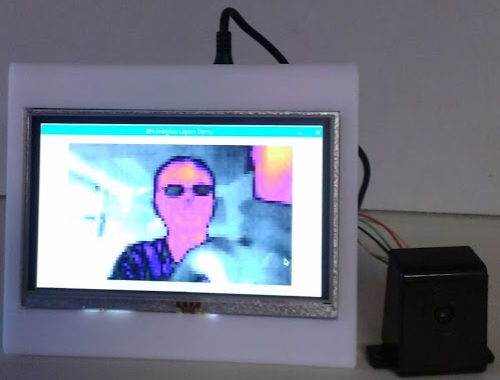
A Vital Body Condition and Situation Monitoring System (demonstration unit) was developed by The Engineer and presented by Dr. Professor Hodzic to a group of European Safety officials at a meeting in Sarajevo. Interested parties represented Health Care, Public Safety, and Mining sectors, all of them being concerned with the physical well being of first line responders, defenders, and workers exposed to industrial or other hazards.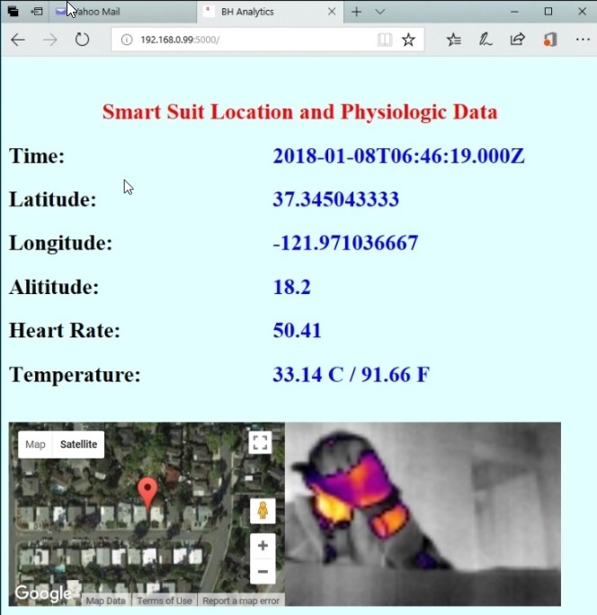 The system was sewen into a tactical-style vest (as one implementation example) providing a GPS position map with coordinate data, current time readout,
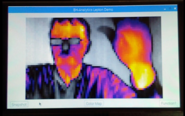
subject's heart rate, body temperature, and a long-wave thermal video camera providing a forward-looking image.
The system was sewen into a tactical-style vest (as one implementation example) providing a GPS position map with coordinate data, current time readout,
subject's heart rate, body temperature, and a long-wave thermal video camera providing a forward-looking image.
 Additional respiration and activity sensor inputs have been provisioned for later integration.
Current data and imaging may be viewed by monitoring
personnel using a standard browser connected to the system's static IP address.
Additional respiration and activity sensor inputs have been provisioned for later integration.
Current data and imaging may be viewed by monitoring
personnel using a standard browser connected to the system's static IP address.
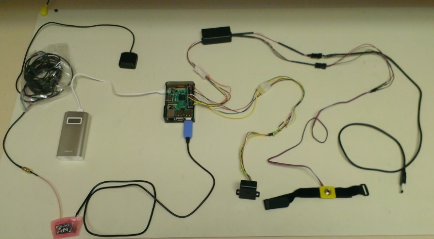
 The system is WiFi connected to a local network
which can be extended to enable secure connection to
the internet with incorporation of additional
firmware. Firmware programming in Python and C++ was
used to build the system, which runs on a Raspberry
Pi 3 platform using the latest Rasbian version OS. The Monitoring System automatically runs at power up, and uses a
portable lithium polymer battery intended to last several hours under continuous use.
The system is WiFi connected to a local network
which can be extended to enable secure connection to
the internet with incorporation of additional
firmware. Firmware programming in Python and C++ was
used to build the system, which runs on a Raspberry
Pi 3 platform using the latest Rasbian version OS. The Monitoring System automatically runs at power up, and uses a
portable lithium polymer battery intended to last several hours under continuous use.
The details of this project have recently been published by The Institution of Engineering and Technology, London, United Kingdom, 2020. See Chapter 1, "Sensor-enabled smart suit electronic IoT design platform with emergency services application" by Migdat Hodzic1, James M. Brennan2 and Enis Dzanic3.
Use "Download" link to review Chapter 1 of book online:
Chapter 1 of Wireless Medical Sensor Networks for IoT-Based EHealth | Fadi Al-TurjmanMedical Ultrasound Zone Imaging Device
 The Engineer was involved in the original research and development for new Zone-based ultrasound imaging technology using the Texas Instruments TMS320C6203.
Work by The Engineer included DSP programming in C and linear assembly language to conduct data acquisition, I-Q dataset formatting,
and ultrasound array beamforming. Early prototype efforts by The Engineer resulted in a direct ultrasound image reconstruction
-- including scan conversion -- of the displayed image composed of a series of Zones.
Computational complexity and speed requirements for this application were enormously demanding, and took full advantage of the
parallel processing architecture of the TI TMS320C6203 operating at nearly its full 2400 MIPS rating to accomplish the required
Phased Array Beamforming. The Engineer later lead DSP group coding efforts to implement advanced beamforming,
software scan conversion, and Color Flow imaging functions. This
new technological approach grew out of US Patents # 6,251,073 and
#6,569,102 co-invented by The Engineer.
The Engineer was involved in the original research and development for new Zone-based ultrasound imaging technology using the Texas Instruments TMS320C6203.
Work by The Engineer included DSP programming in C and linear assembly language to conduct data acquisition, I-Q dataset formatting,
and ultrasound array beamforming. Early prototype efforts by The Engineer resulted in a direct ultrasound image reconstruction
-- including scan conversion -- of the displayed image composed of a series of Zones.
Computational complexity and speed requirements for this application were enormously demanding, and took full advantage of the
parallel processing architecture of the TI TMS320C6203 operating at nearly its full 2400 MIPS rating to accomplish the required
Phased Array Beamforming. The Engineer later lead DSP group coding efforts to implement advanced beamforming,
software scan conversion, and Color Flow imaging functions. This
new technological approach grew out of US Patents # 6,251,073 and
#6,569,102 co-invented by The Engineer.
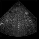
40 MHz Ultrasound Imaging Guide Wire
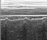
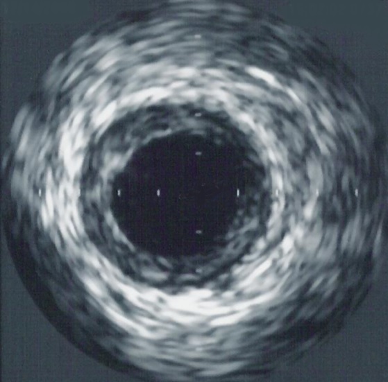
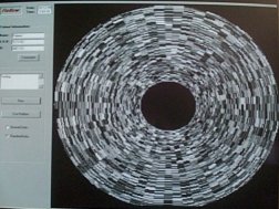 The Engineer designed the display and processing software used by this device intended to provided a method
for the physician to visually cross coronary occlusions within the lumen.
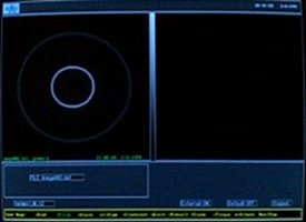
Initial display wide angle test pattern (shown left) and
final product display screen format (shown right) are depicted in these
image slides. The final product display contained a frozen saved image
in the left panel for comparison to the real time image in the right panel.
This PC based system had a full complement of user adjusted
controls including front-end Gain, image Slope, and Contrast.
The Engineer designed the display and processing software used by this device intended to provided a method
for the physician to visually cross coronary occlusions within the lumen.
Initial display wide angle test pattern (shown left) and
final product display screen format (shown right) are depicted in these
image slides. The final product display contained a frozen saved image
in the left panel for comparison to the real time image in the right panel.
This PC based system had a full complement of user adjusted
controls including front-end Gain, image Slope, and Contrast.
 Several
catheter wire profiles were accepted that allowed adjustment of defaults
based on specific guide-wire configuration.
All programming was done
by The Engineer in C and assembly language to operate on a PC-based
platform. The objective of this system was to allow a guide wire tip
to present a forward-looking ultrasound "view" of coronary artery occlusion, and
of the open lumen beyond. This allowed the physician to
carefully navigate the guide wire sized probe tip through the occluding
tissue with hand movements, thus opening the blocked coronary
artery sufficiently to allow larger catheter entry for more advanced therapy. The unit underwent animal trials at
a controlled facility, after which all technology was purchased by a prominent medical catheter company.
Several
catheter wire profiles were accepted that allowed adjustment of defaults
based on specific guide-wire configuration.
All programming was done
by The Engineer in C and assembly language to operate on a PC-based
platform. The objective of this system was to allow a guide wire tip
to present a forward-looking ultrasound "view" of coronary artery occlusion, and
of the open lumen beyond. This allowed the physician to
carefully navigate the guide wire sized probe tip through the occluding
tissue with hand movements, thus opening the blocked coronary
artery sufficiently to allow larger catheter entry for more advanced therapy. The unit underwent animal trials at
a controlled facility, after which all technology was purchased by a prominent medical catheter company.
Ultrasound Cardiac Catheter A-Mode ranging software and hardware
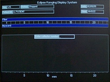 The engineer designed some of the hardware and most of the software for this laser fiber-optic TMR application.
The main program written by The Engineer provided measurement of the laser fiber penetration depth (in millimeters)
into myocardial wall of the heart. Several parameters were tracked in real-time: a) surface of myocardial wall and
catheter contact point; b) actual depth of laser fiber tip (using a reflective collar) into myocardium;
and c) outer myocardial wall depth (needed to prevent perforation). Range indication was derived using
ultrasound A-Mode data acquisition and processing. Filtering and peak detection algorithms were employed to
compute depth between laser fiber tip (using ultrasound reflective collar) and outer wall of the heart to prevent
penetration. System tracked distance between laser fiber tip and outer wall in real-time, thus alerting user and
shutting off laser when distance became less than desired adjustable threshold. The Engineer designed all software
in C language, as well as accompanying digital hardware interface. All software was done under FDA software
development protocol requirements, and documented accordingly. The Engineer also built, debugged, and tested
five complete prototype units, then helped transfer them to customer for clinical trials to be held in Europe.
The engineer designed some of the hardware and most of the software for this laser fiber-optic TMR application.
The main program written by The Engineer provided measurement of the laser fiber penetration depth (in millimeters)
into myocardial wall of the heart. Several parameters were tracked in real-time: a) surface of myocardial wall and
catheter contact point; b) actual depth of laser fiber tip (using a reflective collar) into myocardium;
and c) outer myocardial wall depth (needed to prevent perforation). Range indication was derived using
ultrasound A-Mode data acquisition and processing. Filtering and peak detection algorithms were employed to
compute depth between laser fiber tip (using ultrasound reflective collar) and outer wall of the heart to prevent
penetration. System tracked distance between laser fiber tip and outer wall in real-time, thus alerting user and
shutting off laser when distance became less than desired adjustable threshold. The Engineer designed all software
in C language, as well as accompanying digital hardware interface. All software was done under FDA software
development protocol requirements, and documented accordingly. The Engineer also built, debugged, and tested
five complete prototype units, then helped transfer them to customer for clinical trials to be held in Europe.
M-Mode Ultrasound Imaging Software
 The Engineer wrote ultrasound data acquisition software in C and assembly language for operation on a PC platform.
Project work involved use of a very high speed Gage data acquisition board to provide M-Mode buffers for the
digitized ultrasound. Special high speed image display software, written by another consultant, was then integrated
into system to provide real-time M-Mode style display. The purpose of this system was to measure the depth of cut in
uterine tissue during a resection procedure. The Engineer also provided digital designs for interface to ultrasound
control electronics. Prototype system was delivered on time to customer under a very tight schedule.
The Engineer wrote ultrasound data acquisition software in C and assembly language for operation on a PC platform.
Project work involved use of a very high speed Gage data acquisition board to provide M-Mode buffers for the
digitized ultrasound. Special high speed image display software, written by another consultant, was then integrated
into system to provide real-time M-Mode style display. The purpose of this system was to measure the depth of cut in
uterine tissue during a resection procedure. The Engineer also provided digital designs for interface to ultrasound
control electronics. Prototype system was delivered on time to customer under a very tight schedule.
Cardiovascular Imaging Software
 The Engineer was responsible for five update releases of 68000-based real-time operating system software for a
cardiac catheter IVUS medical ultrasound imaging system. This system used a mechanically rotating mirror to
project the ultrasound radially making the image. A persistent operatonal problem associated with freezing the
real time image was solved by The Engineer. This problem stemmed from the fact that each image frame had slightly
different specular effects due to the system ultrasound characteristics, which made the individual frames grainy
in appearance. When in real time operation the image was integrated by hardware over several frames prior to display.
However, this integration was not present when an instantenous image was frozen. This problem was fixed by modifying
the software to use a recursive filter on frames stored in memory to duplicate that of the real time hardware.
Other projects were modifying the scan converter to allow for linear vs circular imaging to accommodate linear
pull-back during athrectomy.
The Engineer was responsible for five update releases of 68000-based real-time operating system software for a
cardiac catheter IVUS medical ultrasound imaging system. This system used a mechanically rotating mirror to
project the ultrasound radially making the image. A persistent operatonal problem associated with freezing the
real time image was solved by The Engineer. This problem stemmed from the fact that each image frame had slightly
different specular effects due to the system ultrasound characteristics, which made the individual frames grainy
in appearance. When in real time operation the image was integrated by hardware over several frames prior to display.
However, this integration was not present when an instantenous image was frozen. This problem was fixed by modifying
the software to use a recursive filter on frames stored in memory to duplicate that of the real time hardware.
Other projects were modifying the scan converter to allow for linear vs circular imaging to accommodate linear
pull-back during athrectomy.
Ultrasound Spectrum Analyzer
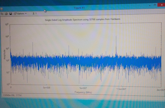 A high speed (40MHz) high bit
density (16-bit) ultrasound data acquisition hardware and processing software system was
designed by The Engineer for a proprietory application. This early
prototype provided a platform for collection of ultrasonic data used for
further development of a sophistocated detection algorithm that monitored for the
presence of cavitation bubbles in cleaning and sterilization baths.
This work later led to the development of a fully self contained
instrument to which the Engineer contributed hardware and
software designs.
A high speed (40MHz) high bit
density (16-bit) ultrasound data acquisition hardware and processing software system was
designed by The Engineer for a proprietory application. This early
prototype provided a platform for collection of ultrasonic data used for
further development of a sophistocated detection algorithm that monitored for the
presence of cavitation bubbles in cleaning and sterilization baths.
This work later led to the development of a fully self contained
instrument to which the Engineer contributed hardware and
software designs.
Prototype Ultrasonic-aided Drug Delivery System for Gene Therapy
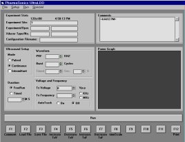 The Engineer designed, configured the system hardware, and wrote software to control several National Instruments hardware boards
that allowed for highly flexible selection of frequency, amplitude, burst width, and on/off times for this ultrasonic power
delivery system. The software was designed and coded in Visual Basic and C language
for interface to National Instruments NIDAC drivers to control the hardware. The
display showed a graph for duration of applied insonification power vs. time. Ultimately the system reliably
provided a control and data acquisition platform for several animal studies using this new ultrasound transducer based
drug delivery technology.
The Engineer designed, configured the system hardware, and wrote software to control several National Instruments hardware boards
that allowed for highly flexible selection of frequency, amplitude, burst width, and on/off times for this ultrasonic power
delivery system. The software was designed and coded in Visual Basic and C language
for interface to National Instruments NIDAC drivers to control the hardware. The
display showed a graph for duration of applied insonification power vs. time. Ultimately the system reliably
provided a control and data acquisition platform for several animal studies using this new ultrasound transducer based
drug delivery technology.
Medical Ultrasound Doppler Movement Detector
 This device was designed by The Engineer to detect applicator movement over
the skin surface during therapeutic HIFU treatment (liposuction replacement).
Prototype Doppler In-phase and Quadrature output provided a novel display mode
which was plotted in polar coordinates to detect very small position movements to a fraction of a wavelength.
System and circuits designed by The Engineer made use of an FPGA for burst and timing generation, switched linear PA
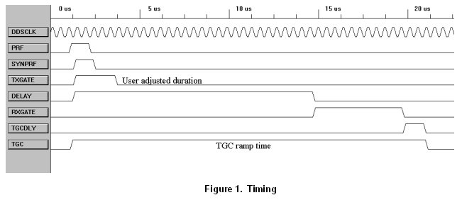
amplifier, sensitive Doppler front-end with TGC ramp, quadrature demodulation including sample and hold circuits, and output display stages.
This prototype system was used as a reference against which other movement technologies were later assessed.
This device was designed by The Engineer to detect applicator movement over
the skin surface during therapeutic HIFU treatment (liposuction replacement).
Prototype Doppler In-phase and Quadrature output provided a novel display mode
which was plotted in polar coordinates to detect very small position movements to a fraction of a wavelength.
System and circuits designed by The Engineer made use of an FPGA for burst and timing generation, switched linear PA
amplifier, sensitive Doppler front-end with TGC ramp, quadrature demodulation including sample and hold circuits, and output display stages.
This prototype system was used as a reference against which other movement technologies were later assessed.
High Intensity Focused Ultrasound
 The Engineer developed all of the electronic hardware/software and interfaces to provide
ultrasound based (HIFU) therapy and progressive treatment imaging for the emerging medical GI market.
This prototype device, built by The Engineer for EndoVx, Inc., was able to alternately provide one sweep of B-Mode imaging,
followed by a timed HIFU ablation period, giving the user a real-time assessment of treatment progress at 15 fps.
Timing was controlled by a PIC18F253 processor and coded in C language.
RF power (up to 143 Watts) and frequency were generated by internal hardware configured and designed by The Engineer.
Animal studies indicated that the desired esophagus tissue affects were being delivered by this instrument and satisfied
hardware and software performance goals set by company.
The Engineer developed all of the electronic hardware/software and interfaces to provide
ultrasound based (HIFU) therapy and progressive treatment imaging for the emerging medical GI market.
This prototype device, built by The Engineer for EndoVx, Inc., was able to alternately provide one sweep of B-Mode imaging,
followed by a timed HIFU ablation period, giving the user a real-time assessment of treatment progress at 15 fps.
Timing was controlled by a PIC18F253 processor and coded in C language.
RF power (up to 143 Watts) and frequency were generated by internal hardware configured and designed by The Engineer.
Animal studies indicated that the desired esophagus tissue affects were being delivered by this instrument and satisfied
hardware and software performance goals set by company.
Medical Blood Assay Measurement Device
 This wide dynamic range optical system designed by the Engineer used a CCD imaging element to measure the video
contrast ratio found in an analyte specimen. A novel technique was
used to display and analyze the optical reflective density with respect to reference
background area approaching 72dB.
The Engineer designed CCD hardware and provided interface, visual display, and analysis software.
The underlying principle of this instrument was to measure the total amount of antibody present in an analyte specimen
that used gold nanospheres bonded to reactive "anti-antibodies".
This wide dynamic range optical system designed by the Engineer used a CCD imaging element to measure the video
contrast ratio found in an analyte specimen. A novel technique was
used to display and analyze the optical reflective density with respect to reference
background area approaching 72dB.
The Engineer designed CCD hardware and provided interface, visual display, and analysis software.
The underlying principle of this instrument was to measure the total amount of antibody present in an analyte specimen
that used gold nanospheres bonded to reactive "anti-antibodies".
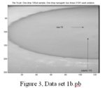
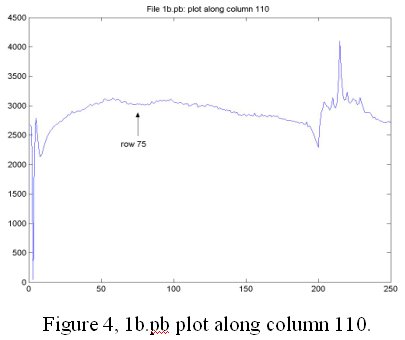 The trace amount of gold nanospheres remaining after
washing was then measured using the designed system and
optics to produce a quantified result. Figure 4 graph
clearly shows reflectivity decrease in curve (at arrow),
indicating the concentration of gold nanospheres bonded to
original analyte. Final system allowed user to adjust
crosshairs over a region of interest to obtain a reflective
quantification index that was related to the amount of
antibody present in the sample. The overarching purpose
of this instrument was for detection of antigens within the sample by measuring the level of antibodies present, and thus detecting
the presence of an antigen.
The trace amount of gold nanospheres remaining after
washing was then measured using the designed system and
optics to produce a quantified result. Figure 4 graph
clearly shows reflectivity decrease in curve (at arrow),
indicating the concentration of gold nanospheres bonded to
original analyte. Final system allowed user to adjust
crosshairs over a region of interest to obtain a reflective
quantification index that was related to the amount of
antibody present in the sample. The overarching purpose
of this instrument was for detection of antigens within the sample by measuring the level of antibodies present, and thus detecting
the presence of an antigen.
Cardiac Catheter Positioning Device
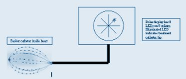 This 68HC11E microprocessor-based medical device firmware accurately tracked and helped position a cardiac catheter tip during an
r.f. ablation procedure. Software-controlled a.c. stimulus signal probe tip was applied to 64 channels
of basket catheter electrodes positioned within the cardiac
chamber. Diagnostic catheter (not shown in diagram) provided variable
impedance path between any two adjacent electrodes, thereby marking its
location. LED display on one of 8 splines would then illuminate when impedance
threshold was crossed, thus marking ablation catheter tip within the chamber. All software work was done in C and Assembly
language for 68HC11 platform. The Engineer worked to modify, correct, and add
several new algorithms to the existing software operating system. A much needed watch dog
timer was added to the software as well as several safety mechanisms to
monitor the weak a.c. stimulus signal used to detect ablation catheter
position. The Engineer also added to, and finalized, the required FDA
software documents for the product prior to delivery to customer.
This 68HC11E microprocessor-based medical device firmware accurately tracked and helped position a cardiac catheter tip during an
r.f. ablation procedure. Software-controlled a.c. stimulus signal probe tip was applied to 64 channels
of basket catheter electrodes positioned within the cardiac
chamber. Diagnostic catheter (not shown in diagram) provided variable
impedance path between any two adjacent electrodes, thereby marking its
location. LED display on one of 8 splines would then illuminate when impedance
threshold was crossed, thus marking ablation catheter tip within the chamber. All software work was done in C and Assembly
language for 68HC11 platform. The Engineer worked to modify, correct, and add
several new algorithms to the existing software operating system. A much needed watch dog
timer was added to the software as well as several safety mechanisms to
monitor the weak a.c. stimulus signal used to detect ablation catheter
position. The Engineer also added to, and finalized, the required FDA
software documents for the product prior to delivery to customer.
Transcranial and Vascular Doppler Spectrum Analyzer
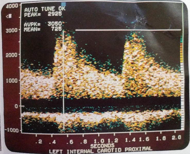 Many years ago, a first generation Doppler Spectrum Analyzer was designed by The Engineer, and a consultant, in the unprecedented time frame
of five months from start to initial prototype operational demonstration. This marathon design session was later analyzed by engineering management with a conclusion that
the secret to successful break-through projects is to put two engineers in a room, give them whatever they need to succeed, and
leave them alone. It was also stated that the right engineers were required for this to be a successful campaign, especially against
existing competition who had already announced a similar, albeit less featured product. The SP25 went on to be the most successful
product of the company ever, with subsequent models including color spectral presentation. The company also benefited greatly from
this product being sold on an O.E.M. basis to many major medical ultrasound imaging companies. This same spectrum analysis engine was
later integrated by The Engineer into a Transcranial Doppler product, which was used to visualize blood flow within the circle of Willis in the brain.
Many years ago, a first generation Doppler Spectrum Analyzer was designed by The Engineer, and a consultant, in the unprecedented time frame
of five months from start to initial prototype operational demonstration. This marathon design session was later analyzed by engineering management with a conclusion that
the secret to successful break-through projects is to put two engineers in a room, give them whatever they need to succeed, and
leave them alone. It was also stated that the right engineers were required for this to be a successful campaign, especially against
existing competition who had already announced a similar, albeit less featured product. The SP25 went on to be the most successful
product of the company ever, with subsequent models including color spectral presentation. The company also benefited greatly from
this product being sold on an O.E.M. basis to many major medical ultrasound imaging companies. This same spectrum analysis engine was
later integrated by The Engineer into a Transcranial Doppler product, which was used to visualize blood flow within the circle of Willis in the brain.
Magneto Optic Imaging
 A first-ever Magneto-Optic Imaging system was designed and built
by The Engineer for a physist inventor (Gerald Fitzpatrick) to exploit an interesting and obscure scientific
phenomenon. The specific phenomenon took advantage of a thin film of bismuth-doped iron garnet having magnetic anisotropy as well as a high degree of
Faraday rotation. This allowed the bismuth-doped iron garnet to sense magnetic fields, and transfer its domain information by way
of polarized light to be visualized. Fitzpatrick needed a system that would produce an extremely high current sheet that switched
at 10KHz to 50KHz as a stimulus for producing uniform magnetic currents under the garnet disk. The garnet disk would in turn be illuminated by polorized light with a video
camera focused on it. The overarching purpose of this system was to detect magnetically induced eddy currents that were generated by discontinuous
cracks in the aluminum skin of aircraft wing and body parts.
A first-ever Magneto-Optic Imaging system was designed and built
by The Engineer for a physist inventor (Gerald Fitzpatrick) to exploit an interesting and obscure scientific
phenomenon. The specific phenomenon took advantage of a thin film of bismuth-doped iron garnet having magnetic anisotropy as well as a high degree of
Faraday rotation. This allowed the bismuth-doped iron garnet to sense magnetic fields, and transfer its domain information by way
of polarized light to be visualized. Fitzpatrick needed a system that would produce an extremely high current sheet that switched
at 10KHz to 50KHz as a stimulus for producing uniform magnetic currents under the garnet disk. The garnet disk would in turn be illuminated by polorized light with a video
camera focused on it. The overarching purpose of this system was to detect magnetically induced eddy currents that were generated by discontinuous
cracks in the aluminum skin of aircraft wing and body parts.
The Engineer designed the first prototype electronics and gate-array firmware, then built and delivered five working devices
in production quality chassis. These prototype units were
evaluated and put into effective use by several aircraft companies. The device was subsequently featured on a Japanese television documentary
which praised it as a major discovery to help
combat hidden corrosion in aging aircraft throughout the world.
Wireless Networking Patent
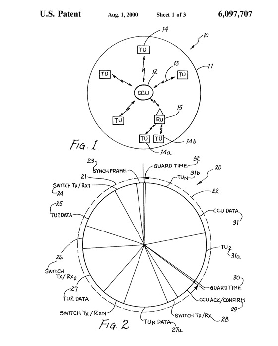 A novel wireless digital communication network comprised of a central control unit and
multiple remote terminal units with multiple access was envisioned, and then built with help from The
Engineer. Various system blocks including RF circuitry, digital control, and software were
implemented (with The Engineer contributing in all areas at this three man starup) and then tested in the lab and at a remote location to prove feasability. One
of the novel aspects of this system was its scheduling method, which managed and optimized
throughput using a novel reservation method. US Patent
#6097707 was issued to The Engineer as co-inventer of this system.
A novel wireless digital communication network comprised of a central control unit and
multiple remote terminal units with multiple access was envisioned, and then built with help from The
Engineer. Various system blocks including RF circuitry, digital control, and software were
implemented (with The Engineer contributing in all areas at this three man starup) and then tested in the lab and at a remote location to prove feasability. One
of the novel aspects of this system was its scheduling method, which managed and optimized
throughput using a novel reservation method. US Patent
#6097707 was issued to The Engineer as co-inventer of this system.
Not only did the radio hardware support the patented TDMA and scheduling method, but it transmitted on an ISM band utilizing BPSK with an 11-bit Direct Sequence Spread Spectrum Technique. It should be noted that Direct Sequence Spread Spectrum is more difficult to code and decode over the much greater used frequency hopping techniques employed in modern equipment. The Engineer was also instrumental in successfully completing FCC testing which required additional hardware tweaking to achieve the required 10.4dB processing gain for the system.
Wi-Fi Connected Tablets
 The Engineer was instrumental in making major hardware design changes to a Wi-Fi connected tablet used in
the hospital environment, which allowed physician access to patient records over a secure wireless
thin client LAN. This product had also found use in commercial, industrial, O.E.M, and government settings
with thousands of units purchased. The original Strong Arm SA1110 based
system was re-designed by The Engineer, and other consultants, to use a low power Geode LX
800 processor. The design embodied all original product functions and
included built-in 802.11g wireless LAN thin client capability and
12 inch TFT display. After significant design efforts, The Engineer successfully undertook new board "bring-up", solving
problems associated with the new design including: boot configuration; flash and DDR memory;
TFT LCD display and touch screen; USB interface; Audio hardware; Lithium
battery charging issues; and EMI suppression requiring switching power supply modifications.
Additional efforts included working with off-shore
suppliers to customize other special purpose tablets targeted
for industrial, gaming, and defense industries.
The Engineer was instrumental in making major hardware design changes to a Wi-Fi connected tablet used in
the hospital environment, which allowed physician access to patient records over a secure wireless
thin client LAN. This product had also found use in commercial, industrial, O.E.M, and government settings
with thousands of units purchased. The original Strong Arm SA1110 based
system was re-designed by The Engineer, and other consultants, to use a low power Geode LX
800 processor. The design embodied all original product functions and
included built-in 802.11g wireless LAN thin client capability and
12 inch TFT display. After significant design efforts, The Engineer successfully undertook new board "bring-up", solving
problems associated with the new design including: boot configuration; flash and DDR memory;
TFT LCD display and touch screen; USB interface; Audio hardware; Lithium
battery charging issues; and EMI suppression requiring switching power supply modifications.
Additional efforts included working with off-shore
suppliers to customize other special purpose tablets targeted
for industrial, gaming, and defense industries.
Thermographic Imaging
 After being commissioned by a university professor who was conducting research at a prominant European institution,
The Engineer engaged into a scientific investigation on thermographic imaging
for medical and other industrial purposes. A specialized Long Wave Infra Red
(LWIR) camera and imaging system was designed and built for the purpose of evaluating its
sensitivity to human thermal emissions related to tumor growth,
and elevated body temperatures caused by various health related conditions.
When calibrated, a sensitive LWIR camera has a 0.6 degree C resolution at 37 degrees C
(normal adult human body temperature), and is within a linear response range for such measurements.
After being commissioned by a university professor who was conducting research at a prominant European institution,
The Engineer engaged into a scientific investigation on thermographic imaging
for medical and other industrial purposes. A specialized Long Wave Infra Red
(LWIR) camera and imaging system was designed and built for the purpose of evaluating its
sensitivity to human thermal emissions related to tumor growth,
and elevated body temperatures caused by various health related conditions.
When calibrated, a sensitive LWIR camera has a 0.6 degree C resolution at 37 degrees C
(normal adult human body temperature), and is within a linear response range for such measurements.
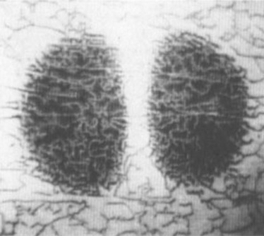
 During the investigation it was determind that even a slight body temperature differential,
such as that found between a peripheral blood vessel and its surrounding tissues, may be
differentiated by the imaging system that had been built. Based upon this, it was also determined that
the system would be useful
in detecting the relative health of an individual, aside from the more focused condition of
differentiating sections of vasculature. It should be noted (in the included image)
how temperature differences
between the wrist, palm, and digits can be marked by a represented false color gradient.
Following successful demonstration of the device, it was concluded that more investigation
and research was warranted on this leading edge technology to identify other medical and industrial
applications.
During the investigation it was determind that even a slight body temperature differential,
such as that found between a peripheral blood vessel and its surrounding tissues, may be
differentiated by the imaging system that had been built. Based upon this, it was also determined that
the system would be useful
in detecting the relative health of an individual, aside from the more focused condition of
differentiating sections of vasculature. It should be noted (in the included image)
how temperature differences
between the wrist, palm, and digits can be marked by a represented false color gradient.
Following successful demonstration of the device, it was concluded that more investigation
and research was warranted on this leading edge technology to identify other medical and industrial
applications.
Secure Area Access and Direction
 A safe and secure method was needed to monitor and provide
crowd control and personal access with routing direction in a very large
complex.
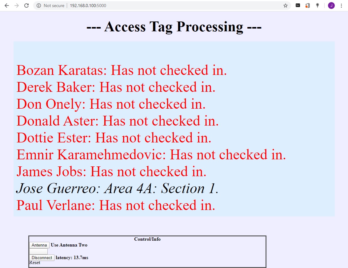
The Engineer was commissioned to develop a demonstration system that met initial specifications with this primary objective of
crowd safety and security. The finished single station demonstration system uses an RFID reader to query small identification
wristband tags assigned to and worn
by the attendees. Individuals wearing identification
tags outside of the complex are detected and marked with a "Has not checked in" status.
When they pass by the entrance station they are marked as "Checked in"
and provided instructions to their
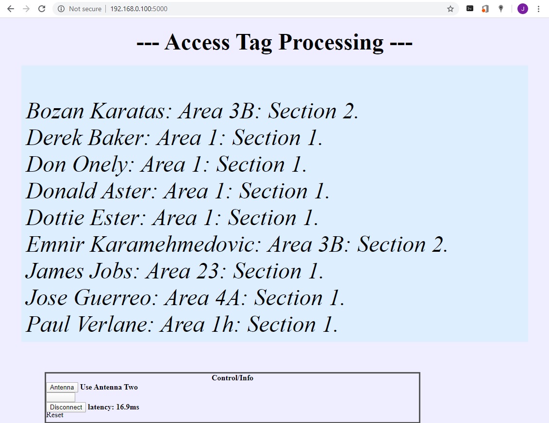
next directed destination. The system is designed
so that multiple stations, each with short-range and long-range antennas throughout the
complex, identify the users and provide information to them
along the way as well as tracking them in route to an expected destination. A database keeps a record of the
users and their location, which is accessable to security personnel.
A safe and secure method was needed to monitor and provide
crowd control and personal access with routing direction in a very large
complex.
The Engineer was commissioned to develop a demonstration system that met initial specifications with this primary objective of
crowd safety and security. The finished single station demonstration system uses an RFID reader to query small identification
wristband tags assigned to and worn
by the attendees. Individuals wearing identification
tags outside of the complex are detected and marked with a "Has not checked in" status.
When they pass by the entrance station they are marked as "Checked in"
and provided instructions to their
next directed destination. The system is designed
so that multiple stations, each with short-range and long-range antennas throughout the
complex, identify the users and provide information to them
along the way as well as tracking them in route to an expected destination. A database keeps a record of the
users and their location, which is accessable to security personnel.
 The Engineer designed hardware configuration and
software for this currently operational demonstration system (ultimately
expanding to hundreds of stations), with each station comprised of a microcomputer board directly controlling an Impinj Indy
R2000-based RFID reader. Custom software control
was written in Python for a linux SBC and uses two
completely separate applications running concurrently with
a proprietory communications link to keep them
synchronized. One application is the main RFID reader
controller, which captures user IDs as they pass by
long-range antennas. The other application is a Flask
socket-IO web server, which not only provides the user
interface and local feedback to a user ID, but also allows
remote web clients in a control room access to a specific
station's status and ID's captured. The local system
is also connected to an external database server providing
information about all stations to keep track of all user
ID's and their locations.
The image at right shows example user name and next destination
within the complex.
The Engineer designed hardware configuration and
software for this currently operational demonstration system (ultimately
expanding to hundreds of stations), with each station comprised of a microcomputer board directly controlling an Impinj Indy
R2000-based RFID reader. Custom software control
was written in Python for a linux SBC and uses two
completely separate applications running concurrently with
a proprietory communications link to keep them
synchronized. One application is the main RFID reader
controller, which captures user IDs as they pass by
long-range antennas. The other application is a Flask
socket-IO web server, which not only provides the user
interface and local feedback to a user ID, but also allows
remote web clients in a control room access to a specific
station's status and ID's captured. The local system
is also connected to an external database server providing
information about all stations to keep track of all user
ID's and their locations.
The image at right shows example user name and next destination
within the complex.
Some Other Projects
© Copyright 2023, Cybertronic Engineering - Cybertro.com. Theme by ThemeWagon